1. Introduction
In the coastal and open oceans, various sized eddies play important role in mixing and transporting physical (such as temperature and salinity), chemical (pollutants) and biological properties (planktons) horizontally as well as vertically. Mesoscale eddies with scale range of O(10) ~ O(100) km are especially important in this respect because of the long life and so their coherent structures. These coherent structures of mesoscale eddies has been studied in terms of Eulerian as well as Lagrangian approaches. The spatial structure of eddies are well identified by calculating such as Okubo-Weiss parameters (OW) of instantaneous flow fields (Pasquero and Provenzale, 2002; Isern-Fontanet etal., 2004; Isern-Fontanet et al., 2006). Although it is useful in capturing two-dimensional characteristics of turbulent eddies, however, there is a restriction in this Eulerian approach as it is limited in describing transport of water parcels in and out of eddies or across coherent structures. Thus, Lagrangian approaches have been commonly employed as well due to their advantage in addressing transport problems.
When coherent structures are studied in Lagrangian perspective using fluid trajectories, they are often named Lagrangian Coherent Structures (LCS) (Shadden et al., 2005). The LCS are characterized as transport barriers in unsteady incompressible flows with stable and unstable manifolds of hyperbolic points that act as repelling and attracting material lines and so are responsible for the stretching and folding pattern of passive tracers (Haller and Yuan, 2000; Haller, 2001; Haller, 2002). Since LCS are useful in visualization of time-varying geometric features such as eddies and jets, they are often used to identify the boundaries of mesoscale eddies (d’Ovidio et al. 2004, 2009; Harrison and Glatzmaier, 2012; Bettencour et al., 2012). Two common methods to compute LCS are the finite-scale Lyapunov exponent (FSLE; Artale et al., 1997; Aurell et al., 1997) and similarly the finite-time Lyapunov exponent (FTLE; Haller, 2001) in which the relative dispersion of particles are rated; namely how fast particle pairs separate in a given finite space and time. Both FSLE and FTLE have been widely applied in studying oceanic flows for characterizing dispersion process ( Lacorata et al., 2001; Waugh et al., 2012; Haza et al., 2008, 2010, 2012; Özgökmen et al., 2011, 2012) and also for detecting and visualizing LCS (d’Ovidio et al., 2004, 2009; Olascoaga et al., 2006; Branicki and Kirwan, 2010; Harrison and Glatzmaier, 2012; Bettencourt et al., 2012, 2013) as the maxima (or ridges) of FSLE/FTLE fields provide practical means of identifying the repelling and attracting LCS. Since strong divergence/ convergence occurs along these ridges, they act as material boundary lines of eddies as fluid particles are not to cross these lines. However, since strong mixing is also expected near the hyperbolic points where the stable and unstable manifolds intersect and these hyperbolic points are not fixed in unsteady flows (Olascoaga et al., 2006), there exists a possibility of mass exchange between an eddy and its environment due to such as turnstile lobe mechanism of time-evolving eddies (Branicki and Kirwan, 2010).
In addition, the role of smaller sized LCS has emerged in mixing and transport in the oceanic flows near mesoscale eddies. The submesoscale flows that have scale range of O(100) m ~ O(10) km have been recognized to play critical roles in the energy cascade (Müller et al., 2005; McWilliams, 2008), and in horizontal dispersions at open (Lumpkin and Elipot, 2010) as well as coastal oceans (Schroeder et al., 2012), suggesting significant energy at the submesoscales may dominate surface stirring and dispersion. However, this effect of submesoscale features is not properly reflected in models that do not explicitly resolve submesoscales, which suggest the need of parameterization of submesoscale transport properties (Haza et al., 2012; Özgökmen et al., 2012). Though the submesoscale structures are actively developed in the surface mixed layer due to mixed layer instabilities (Özgökmen et al., 2011, Mensa et al., 2013), they are also found below the mixed layer (Quentel et al., 2010) and may affect the structure of ocean interior as well (Lapeyre et al., 2006). In this respect, contributions of mesoscale as well as submesoscale flow structures on the vertical transport through water columns are of great importance in terms of vertical exchange of various tracers. While there are reports on the significant role of mesoscale eddies on the vertical exchanges (Martin and Richards, 2001; McGillicuddy et al., 2007), the effect of submesoscales are also numerically investigated as high vertical velocities are found at the submesoscale filaments (Lévy et al., 2001; Mahadevan and Tandon, 2006; Capet et al., 2008) and so the productivity may be influenced by these submesoscale structures (Lapeyre and Klein, 2006). Klein and Lapeyre (2009) reviewed the studies on the vertical motions induced by oceanic flow turbulence in which the role of submesoscales in the vertical pumping of biogeochemical tracers may be as much important as the mesoscale eddies while recent numerical experiments by Lévy et al. (2012) shows somewhat unexpected result as the global phytoplankton abundance decreases in the submesoscale-resolving high resolution simulation. Therefore, the role of both mesoscale and submesoscale flow structures in the vertical transport between the surface and interior of the ocean is still an important question to be hopefully answered in the near future owing to the increasing computational capacity that allows high resolution simulations.
The purpose of the present study is to examine the three-dimensional structures of flow fields near mesoscale ocean rings in the Gulf Stream region, generated by the Hybrid Coordinate Ocean Model (HYCOM) (Bleck, 2002; (Halliwell, 2004). Comparisons are made for two different horizontal resolutions: 1/12o (low-resolution) resolving mesoscale structures, and 1/48o (high-resolution) by which submesoscales are partially resolved. Thus the purpose of this study includes investigation of possible effects of small-scale flow structures on the large-scale rings. For this, LCSs of the rings are identified using Lagrangian (FSLE) as well as Eulerian (OW) approaches. Also, two different definitions of vertical dispersion coefficients are applied in order to examine vertical transports associated with flows near the rings.
2. Numerical Experiment
The present study has been carried out using HYCOM to simulate the recirculating region of the Gulf Stream. Numerical experiments are performed by employing two different resolutions with 1/48o and 1/12o horizontal grids. The grid size of the high-resolution model (HR, 1/48o) is ~ 2 km in which submesoscale features can be partially resolved. The low-resolution model (LR, 1/12o) has grid size ~8 km that is too coarse to resolve submesoscales. The 1/12o simulation originally covers the Atlantic Ocean and Mediterranean Sea in the latitude range between 28oS and 80oN (Chang et al., 2009). The 1/48o simulation is performed in a nested domain (ig. 1), covering the Gulf Stream region from 81.44oW, 28.78oN to 50.0oW, 45.72oN (Mensa et al., 2013). The nested simulation is integrated for 18 months after it is initiated from the 1/12o solution on January 1, after 8 years spin-up of the LR model. The numerical experiment of the present study is based on Mensa et al. (2013) and the readers are referred to that article for more details on the model configuration. However, it should be pointed out that the vertical velocity components are additionally calculated from the original HYCOM outputs that have isopycnal vertical coordinate system in the ocean interior. The vertical velocity components are calculated in Zvertical coordinates from the continuity equation.
The analysis was done by selecting rings from the instantaneous flow fields of each resolution out of the 18-month data sets. The flow fields are chosen at May 24 and Sep. 27 of the first year for the low- and high-resolution simulations, by considering three conditions. First, although the chosen days between the two resolutions do not have to be identical, they are required to be from same season. Mensa et al. (2013) shows that the structure of surface submesoscale features has a strong seasonal variation due to the change of mixed layer thickness. During summer, the mixed layer is thinner so the impact of submesoscale features on the large-scale motions is smaller than winter. Thus, we choose the data sets from summer so the mesoscale eddy structures may be identified clearly. The second condition for the choice of the rings is the duration of ring existence. Since the analysis of LCSs of the rings based on the Lagrangian method includes time integration of trajectories of passive particles from the chosen instantaneous dates, the identification of LCSs would be easier and their features would be clearer if the rings persist longer. In addition, the four rings are selected to be within comparable ranges of flow energy and eddy vorticity, as compared in Fig. 8.
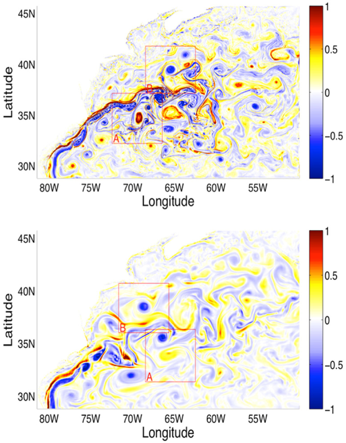
Fig. 1 shows the ocean surface relative vorticity fields for the two resolutions in the nested domain of the Gulf Stream region. In both cases, a collection of different sized cyclonic and anticyclonic rings found, where the cold-core cyclonic rings are usually found on the southern side of the Gulf Stream while warm-core anticyclonic rings are generally found on the northern side, due to the ring formation mechanism of the meandering stream. For each resolution, two subregions were selected. Subregion ‘A’ was chosen on the southern side of the stream with one cyclonic ring within it. Subregion ‘B’ was selected on the northern side and contained one anticyclonic ring. The vorticity field of the HR simulation is more complex than that of the LR simulation, with high variability in the size of flow structures. Many small-sized eddies and filaments are found near the larger mesoscale rings. Although the sizes of these small-scale structures are not confined to the submesoscale category, because many of them are bigger than 10 km, they are much smaller than the size of the chosen rings which have sizes larger than 100 km. In the LR simulation, small-scale structures are rarely found and only the rings are dominant.
Fig. 1.
Relative vorticity fields near the ocean surface normalized by f for 1/48o (upper panel) and 1/12o (lower panel) resolutions. Region ‘A’ ontains cyclonic rings and Region ‘B’ contains anticyclonic rings (This picture is taken from Chang and Park, 2015).
3. Results
3.1 Three-dimensional structure of the rings
As already mentioned, LCSs can be computed using Lyapunov exponents such as FTLE and FSLE based on Eulerian velocity fields. In the present study, we employ FSLE as it has been successfully used in visualization of LCSs of ocean eddies as well as atmospheric vortices (Joseph and Legras, 2002; d’Ovidio et al., 2004; Haza et al., 2008, 2010, 2012; Bettencourt et al., 2013). For example, Joseph and Legras (2002) constructed forward and backward FSLE manifolds superimposed on the potential vorticity map of the Antarctic vortex, finding the vortex to be surrounded by FSLE ridges. With the analogy of a float experiment, the FSLE technique also appears to be suited for oceanographic applications, as zd’Ovidio et al., 2004 used FSLE to characterize mesoscale eddy structures with embedded vortices in them. Bettencourt et al. (2013) calculated three-dimensional FSLE and applied it to oceanic flows simulated with the Regional Ocean Modeling System (ROMS). Haza et al. (2010), comparing with observations from drifters, confirmed that the FSLE ridges act as natural transport barriers; hence the FSLE seems to be an effective tool in mapping the flow field’s natural transport barriers. The FSLE is defined as:
where < τ(δ) > is the average time (over the number of particle pairs) required to separate from a distance of δ to αδ.
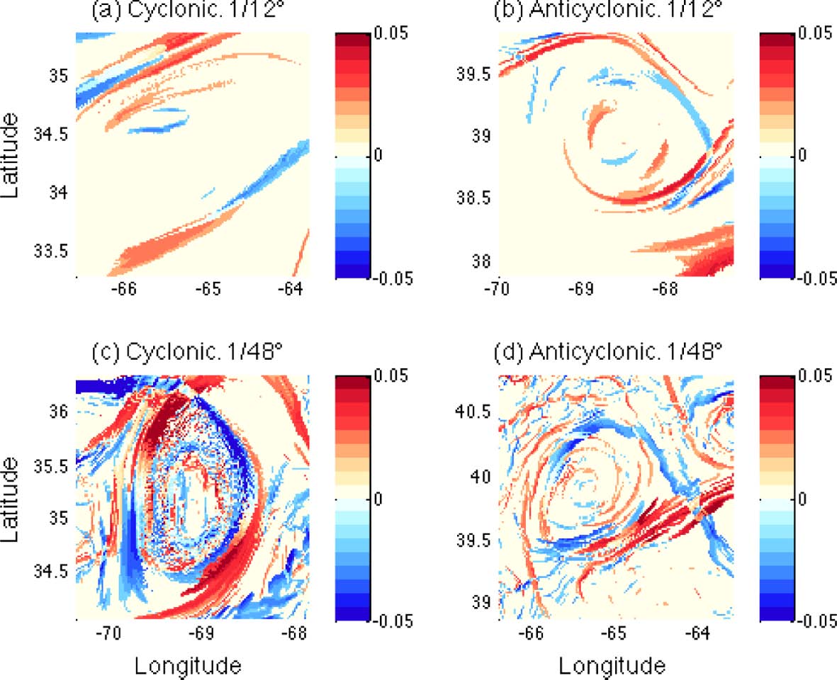
In Figs. 2 and 4, the two-dimensional FSLE are contoured in the horizontal plane at two different depths, and the FSLE structures of the flows near the rings are compared for the two resolutions. In the figures, the horizontal domains that contain the four rings are subsets of four sub-regions, the ‘A’s and ‘B’s in Fig. 1. These subsets are chosen to be large enough to contain FSLE ridges but also small enough to isolate the rings alone so that any possible contamination to the statistics caused from the area outside the ring is minimized. Also, the subsets are selected to have the same size for all four rings, to allow fair comparisons of spatially averaged properties over the subsets.
Fig. 2.
FSLE fields calculated from backward (positive values) and forward (negative values) integration in time near the surface (z = 21 m). Panels (a) and (b) LR, and panels (c) and (d) HR. Left panels cyclonic rings, and right panels anticyclonic rings.
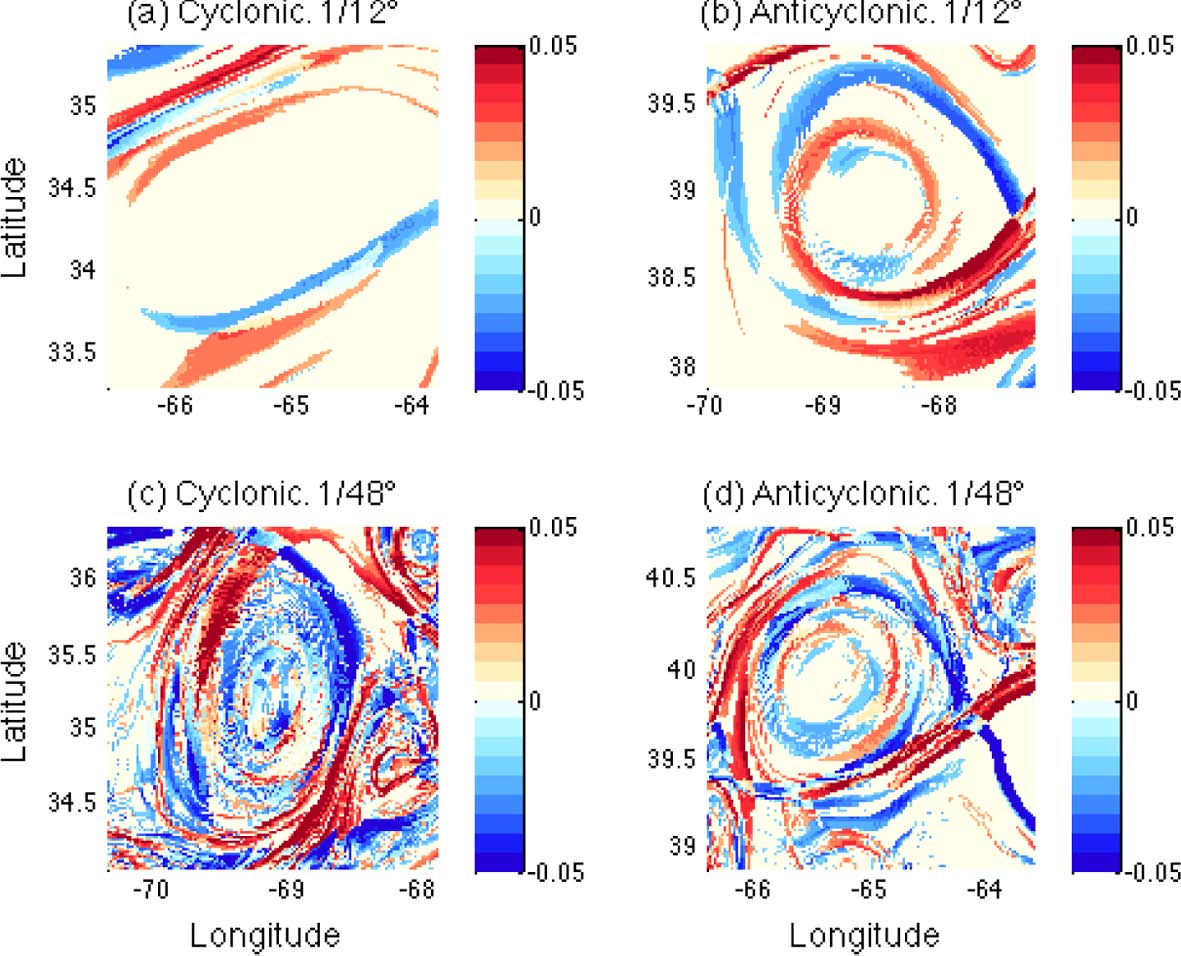
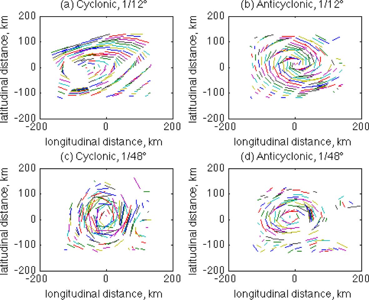
Fig. 3.
Horizontal trajectories of arbitrarily selected particles near the rings for twelve hours. Upper panels LR, lower panels HR. Left panels cyclonic, right panels anticyclonic rings. The particles are initially located at z = 21m.
The horizontal structures of FSLE at the near-surface (z = 21 m) are compared for the cyclonic and anticyclonic rings of HR and LR in Fig. 2. The backward and forward FSLE are integrated in time for five days from the initial times, with α = 10 in Eqn. (1). At every time step, the velocities of passive particles that are not on the grid points are spatially interpolated to calculate the particles’ trajectories. The backward and forward FSLE that have positive and negative values are colored in red and blue respectively. These FSLE structures resemble conventional LCS features that are commonly developed around mesoscale eddies as high values of backward and forward FSLE make pairs that form ridges around the ring centers in all four cases. As reviewed previously, these ridges behave as material walls within the rings and the particles are not allowed to cross these strong convergent/divergent lines. Hyperbolic points at which the backward and forward FSLE ridges intersect are also found in both resolutions, except for the LR cyclonic ring where strong mixing is expected to occur. At the center of the rings (inside the ridges), however, the FSLE magnitudes are generally low especially in the LR case. If the outer FSLE ridges are taken as the eddy boundary, the sizes of the rings are similar. While there is no clear difference found in the FSLE structures between the cyclonic and anticyclonic rings, the difference between the two resolutions is conspicuous. In the two HR rings, many small-scale structures of high FSLE values are found inside and outside the rings. Even the outer boundaries of the rings formed by FSLE ridges are not as clear in the LR rings due to these small structures. The sizes of these small-scale structures are not confined within submesoscales as some of them are larger than 10 km. Due to these small-scale structures, the total FSLE magnitude within the subsets may be higher for HR than LR; this will be discussed in connection with Fig. 5. The FSLE in the LR simulation are much smoother and simpler as only large-scale ridges are found. The backward and forward FSLE ridges of LR anticyclonic rings form a spiral pattern, which may indicate that the particles move in and out of the ring along these convergent and divergent lines considering the clockwise rotation of the ring. Since this spiral pattern is not found in the HR anticyclonic ring, it is not a distinguishing feature of anticyclonic rings.
The small-scale FSLE structures around HR rings may imply important characteristics of particle motions near the rings. For example, there are many local spots with high values of forward FSLE inside the HR cyclonic ring (Fig. 2c). From the definition of forward FSLE, the passive particles in these areas inside the ring would be actively dispersed with high separation rates. Therefore, there could be particles inside that leave the ring, crossing the outer ridges. If this happens, then the role of the outer ridges as a ring boundary of HR rings may be weaker than that for the LR rings because particles in the HR simulation move more irregularly. In order to examine the implications of this, the trajectories of flow particles are compared for the four cases in Fig. 3. The particles are arbitrarily selected around the rings, and the trajectories are obtained by locating the particles twelve hours after leaving their initial positions. As shown in the figure, the particle trajectories are more dispersive in the HR case. For the LR case, particles are nicely following the orbits of the rings, making the orbital trajectories smooth and less dispersive. For the HR case, however, particle motions are less smooth with higher irregularity although they still generally follow the ring orbits.
The three-dimensional structure of FSLE for flows near ocean eddies is of great interest as it may offer clues to an understanding of vertical motions and transport patterns. Recently, a technique has been developed to identify hyperbolic trajectories and FTLE ridges in three-dimensional time dependent flows (Lekien et al., 2007; Branicki and Wiggins, 2009), and it has been applied to identify the three-dimensional LCS structure of ocean eddies by Bettencourt et al. (2013) in which vertical velocity components are included to calculate the three-dimensional FSLE structure of an ocean eddy. Nevertheless, because oceanic flows have stronger horizontal stirring than vertical, their application of three-dimensional FSLE to an ocean eddy did not show clear three-dimensional characteristics. By using only horizontal flow velocities, Branicki and Kirwan (2010) also built a three-dimensional FTLE structure of an ocean eddy using quasi-two-dimensional analysis. They calculated two-dimensional FTLE from the horizontal velocity field at 8 different depths to construct the three-dimensional eddy structure, and it had similar characteristics to that of Bencourt et al. (2013). This type of two-dimensional approach to analyze three-dimensional flows can be justified when vertical velocities are small relative to horizontal velocity scales (Mezic and Wiggins, 1994).
In the present study, we also employ Branicki and Kirwan’s quasi two-dimensional method to build the three-dimensionalional structure of the rings. The two-dimensional FSLE are calculated at 18 different depths from 21 m to ~ 900 m using the horizontal velocities. In Fig. 4, the two-dimensional FSLE structures of the flows near the ring are compared in the same domains as Fig. 2 but at z = 300m. In all four cases, the FSLE magnitude is significantly reduced at this depth, below the mixed layer, at the times when the rings are sampled. The structures of FSLE, however, are basically unchanged from the shallow areas. For example, the FSLE ridges that consist of the ring boundaries still remain at this depth at the same locations. For the HR case, the small-scale FSLE structures have been largely smeared out although they still exist. For the LR rings, the difference from the surface is even smaller as small-scale structures are not actively developed at both depths. Thus, the structure of the FSLE ridges remains in the LR case but with reduced magnitudes.
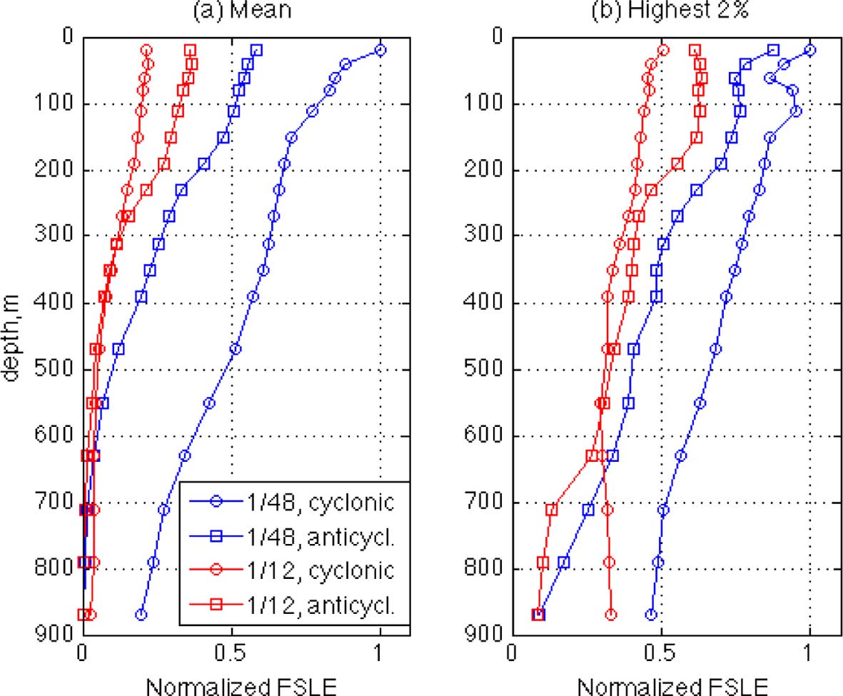
In Fig. 5, the vertical profiles of the relative magnitudes of FSLE for the four rings are compared. In panel (a), the mean values are calculated at 18 depths by averaging over the subset domains and by normalizing with the maximum surface value. The FSLE magnitude sharply decreases with depth for all four cases, and the HR values are larger than the LR values, as expected from the small-scale structures in the HR simulation. Note, in particular, that the FLSE of the HR cyclonic ring shows the highest values at all depths. If compared with the other three rings, the small-scale features are most abundant near the HR cyclonic ring as shown in Figs. 2 and 4, which may lead to its largest mean FSLE values. Since these mean values of the HR simulation are likely due to the small-scale structures, and it seems from Figs. 2 and 4 that the FSLE magnitudes are greater along the large-scale ridges than those of the small-scale, the effect of the small-scale structures can be reduced if the low values of FSLE are filtered. In panel (b) of Fig. 5, the FSLE profiles are compared again after averaging only for the highest 2% of FSLE values. Although the FSLE are still higher in HR, the values in LR are increased so they now become comparable for the two resolutions. This means that the magnitude of FSLE is similar for the HR and LR simulations along the large-scale ridges, and the magnitude difference between the two sides of the ridges is greater for the LR case than the HR case, which implies that the boundaries of the rings constructed by the FSLE ridges may be stronger in the LR simulation. In HR, the flow particles may move with higher freedom near the ridges due to the weaker FSLE spatial gradient.
Fig. 5.
Vertical profiles of FSLE magnitudes, (a) averages over the domains in Figs. 2 and 4, (b) averages of the highest 2% FSLE values only.
In examining eddy structure, another helpful parameter is the Okubo-Weiss parameter (OW). As described in section 1, the usefulness of this Eulerian measure in identifying LCSs is limited. However, it still has been usefully employed to analyze the structure of coherent vortices in two-dimensional turbulent flows (Pasquero et al., 2002; Isern-Fontanet et al., 2004). OW is especially useful in describing eddies because it separates the flow field into two different regions; a vorticity-dominated region (Q < 0) and a strain-dominated region (Q > 0). OW is defined by the difference of strain tensor and relative vorticity of the flows:
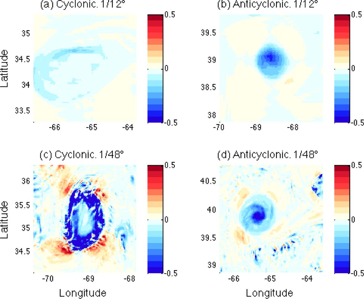
In Fig. 6, the OW fields at z = 21 m are compared between the four rings after the values are normalized by the square of the Coriolis parameter (f 2 ). The ring cores are found at the center of all four rings, as indicated by strong rotations (Q < 0). When compared with Fig. 2, the ring cores are located in the middle of the surrounding FSLE outer ridges. Therefore, the rings have conventional structures with strong rotation occurring at the center but strong divergent/convergent structures occurring along the outer ridges. Apart from this similarity of ring structure, the absolute magnitudes of OW are higher in the HR rings. Considering the definition of OW in Eqn. (2), the higher OW magnitude denotes stronger rotation/deformation occurring in HR than in LR simulations. If the locations of positive OW values in Fig. 6 are compared with the FSLE distribution in Fig. 2, the areas of high strain rate are generally seen to overlap the areas of FSLE ridges, which indicates that the deformation of the rings may occur along the FSLE ridges. This corresponds to the description of the turnstile lobes of time dependent Lagrangian eddies by Branicki and Kirwan (2010) in which deformation of an ocean eddy occurs along the FTLE ridges between the two hyperbolic points due to the action of turnstile lobes, although these ridges remain as material boundaries through the time of eddy evolution. In Fig. 6, the locations of high deformation rates also correspond to the locations of FSLE ridges between the hyperbolic points, which might cause long-term variation of ring geometry although it is not observed during the short term of the present study. Similar to the FSLE, three-dimensional OW structures of the flows near the rings are constructed by applying the same quasi two-dimensional method. The OW fields at z = 300m are shown in Fig. 7 as the OW structure near the surface at z = 21 m remains at this depth without significant change except for the decrease in magnitudes. Similarly to the FSLE fields, the OW structure is much smoother in the LR simulation while many small-scale OW structures are found in the HR simulation.
Fig. 6.
Horizontal distributions of the Okubo-Weiss parameter at z = 21 m, normalized by f2. Upper panels LR, lower panels HR. Left panels cyclonic, right panels anticyclonic rings.
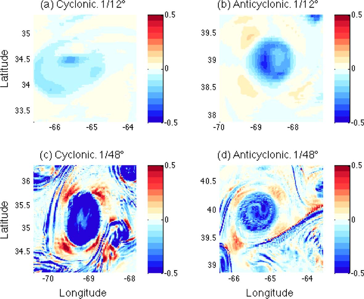
Fig. 8.
Vertical profiles of averaged magnitudes of (a) relative vorticity normalized by the Coriolis parameter, f, and (b) horizontal kinetic energy
(( u 2 ─ + v 2 ─ ) / 2 )
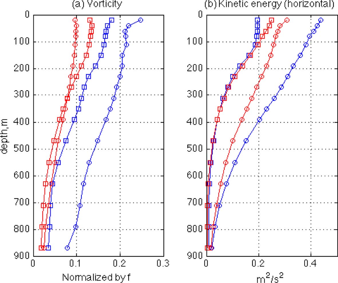
The vertical structure of the rings is also investigated by calculating magnitudes of the relative vorticity and the horizontal kinetic energy. Fig. 8 shows vertical profiles of averaged values of both quantities plotted at the same 18 depths. As expected from the OW distributions in which vorticity magnitude is partly reflected, the magnitude of the LR vorticity is smaller than that of the HR vorticity. It is interesting to see that the vorticity magnitudes of the four rings are arranged in the same order as the FSLE magnitude profiles in Fig. 5, with the highest values in the HR cyclonic ring and the lowest values in the LR cyclonic ring for both quantities except that the lowest values are in the LR anticylconic ring at depths greater than 300 m. In between, the HR anticyclonic rings have values greater than the LR anticyclonic rings at all depths. The similarity between the vorticity and FSLE profiles indicates that the strength of eddy rotation can be related to the strength of eddy boundaries such that stronger rotation may produce a stronger eddy boundary. This is so because a faster-rotating eddy core can be separated more readily from the outer flows; thus, the boundary of the eddy can become stronger. In addition, it is also interesting to see that the close relationship between FSLE and vorticity does not apply to the flow energy. In Fig. 8b, which shows vertical profiles of horizontal kinetic energy (( u 2 ─ + v 2 ─ ) / 2
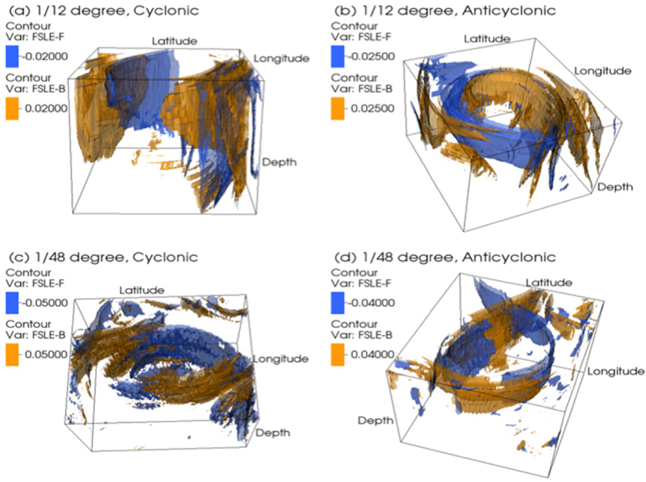
Although the vertical profiles and horizontal distributions of the chosen quantities in the previous figures allow us to make useful comparisons between the rings, they are still not enough to provide sufficient information on the vertical structures. By using the quasi two-dimensional method, three-dimensional structures of the rings are constructed and Figs. 9 and 10 show resulting FSLE and OW isosurfaces. The backward and forward FSLE isosurfaces whose values are chosen for the visualization are colored in orange and blue respectively (Fig. 9). One of the most interesting features of the FSLE structure is the two-dimensionality of the three-dimensional structure in all four rings. The surface structure of the FSLE ridges extends throughout the water column of the domain (z < 900 m) though the ridges get weaker with depth. These FSLE structures form the shape of a ‘vertical curtain’ that has no closure at the bottom. These ‘curtain-shape’ FSLE/FTLE structures of ocean eddies are also found in Branicki and Kirwan (2010) as the instantaneous two-dimensional geometry of the hyperbolic trajectories with stable and unstable manifolds of an ocean eddy extends into the water column from the surface to the base of the eddy (Branicki and Kirwan, 2010). Bettencourt et al. (2013) also report a similar two-dimensionality of the three-dimensional structure with curtain-shaped features of an ocean eddy. This curtain shape of LCS structure denotes that the dispersion process is mainly horizontal. Strong horizontal stirring is present throughout the water column along the FSLE ridges that provide vertical barriers and transport pathways around the eddy, indicating that horizontal dynamics are dominating over vertical motions. Thus, the two-dimensionality of FSLE structure in Fig. 9 also confirms that the vertical motions in these regions are much less intense than horizontal motions, possibly due to strong rotation and stratification.
Fig. 9.
Three-dimensional structure of FSLE isosurfaces for chosen values of forward and backward FSLE. In each case, the FSLE value for the isosurface, as well as the angle of view, has been chosen to maximize ease of visualization.
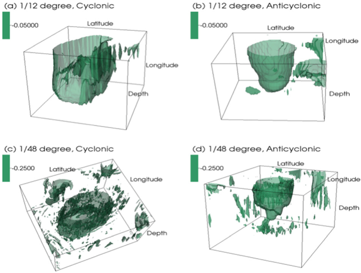
In a similar way, the three-dimensional structure and resulting isosurfaces of the normalized OW are constructed (Fig. 10). Again, the OW isosurface values are chosen individually for the visualization: -0.05 for the LR cases, and -0.25 for the HR cases. Since these values are all negative, however, the OW surfaces in Fig. 10 mainly show rotational features inside the boundaries of the rings. The OW structures are somewhat different from the FSLE structures, as the bottoms of the rings are closed at depth, being ‘bowl-shaped’ instead of ‘curtain-shaped’. This difference between three-dimensional FSLE and OW features is also found in Bettencourt et al. (2013) where a bowl-shaped OW field is surrounded by curtain-shaped FSLE fields. The bowl-shaped features of OW are, however, different between cyclonic and anticyclonic rings. While the bottoms of cyclonic rings are concave like a wine bottle, the anticyclonic rings have convex bottoms. This difference is presumably caused by the rotational direction of the eddies. Since the circulations of cyclonic eddies elevate isopycnal surfaces below the eddy core while those of anticyclonic eddies depress the isopycnal surfaces (Sweeney et al., 2003), the isosurfaces of OW in Fig. 10 seem to correspond to the resulting adjustment of the isopycnal surfaces. This difference in OW shapes may be related to the vertical structure of vorticity and kinetic energy. The areas of OW isosurfaces of anticyclonic rings decrease faster with depth than those of cyclonic rings, which indicates that the strength of the rotational tensor decreases faster in the anticyclonic rings. Similarly, both the vorticity and horizontal kinetic energy profiles in Fig. 8 are seen to decrease with depth more rapidly in the anticyclonic rings. Although the OW parameter is a useful measure for revealing characteristics of eddy structure, its usefulness in capturing the Lagrangian property of flow motions is limited. For example, Bettencourt et al. (2013) show that isosurfaces of OW do not behave as eddy boundaries since flow particles easily cross an OW isosurface while following the convergent ridges of FSLE.
Fig. 10.
Three-dimensional structure of normalized OW isosurfaces for chosen values (LR = -0.05, HR = -0.25). As for the FSLE surfaces in Fig. 9, the values and view angles are selected to maximize ease of visualization.
3.2 Vertical dispersion near the rings
Although horizontal motions in the ocean are much stronger than vertical motions, it is still of great importance to understand vertical motions of flows especially near large-scale ocean eddies, because the impact of these eddies on the transport of physical and biochemical properties is a crucial question related to vertical mixing in the ocean (e.g., Klein and Lapeyre, 2009). Single-particle dispersion or absolute dispersion, ρ, is one measure that has been usefully employed to analyze particle statistics and coherent structures from chaotic trajectories of a large number of particles (e.g., Haza et al., 2012); it is defined as:
where r is the space vector. In the present study, we apply Eqn. (3) in the vertical direction to calculate the absolute vertical dispersion as:
where z is the vertical position of each particle. The related absolute vertical dispersion coefficient is then given as:
Alternative to the absolute dispersion, the relative (or two-particle) dispersion, D2, has been largely used as it is more closely tied to turbulent and scalar mixing in the underlying flow field (Haza et al., 2008; Poje et al., 2010; Waugh et al., 2012; Özgökmen et al., 2012). The relative dispersion is defined as:
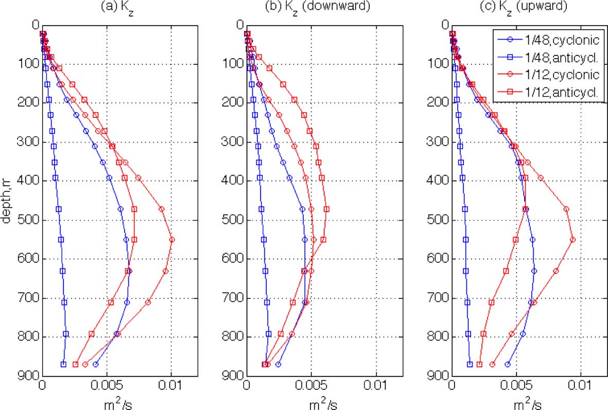
The vertical profiles of Kz for the first 24 hours have been calculated and are shown in Fig. 11a. The magnitudes of K z are somewhat high, as the maximum values reach O(10-2 m2/s) which is about 100 times larger than conventional eddy diffusivity in the ocean interior; this will be discussed later in detail. When values in the four rings are compared, it is found that Kz is larger in the LR rings at most depths. This is interesting because it is generally known that relative dispersion in the horizontal direction increases with finer spatial resolution (Poje at al., 2010). Also, the magnitudes of the other parameters, such as FSLE, OW and vorticities, are greater in HR as shown in the previous figures. Although the horizontal kinetic energy is comparable for the LR and HR cases, the flow energy of LR still does not exceed that of HR. There is, therefore, no reason to expect greater absolute dispersion in the vertical direction for the LR case. To examine this, two additional absolute vertical dispersion coefficients are calculated in panels (b) and (c) of Fig. 11. In panel (b), Kz is calculated only for those particles that move downward during the first 24 hours, and in (c) only for those that move upward. The two groups of particles are separated because the particles near the surface would preferably move down instead of moving up due to the surface restriction (i.e. particles located at shallow depths are easier to move downward rather than upward). Therefore, Kz in panel (b) may reveal the characteristics of vertical dispersion especially for the near surface particles while panel (c) is for the particles interior. As shown in the Fig. 10, the difference in Kz of downward particles between the two resolutions is greater than other two cases at shallow depths. This is possibly caused by the small-scale structures in HR. As shown in Figs. 2 and 4, small-scale features are mainly found at shallow depths and disappear rapidly with depth. Thus, the Kz difference between the two resolutions at shallow depths can be caused mainly by the difference in the development of small-scale structures. As described by Fig. 3, the small-scale structures may cause the higher irregularity of the horizontal particle motions of HR, so they may lead to higher irregularity in the vertical motions as well. Hence, the vertical absolute dispersion rates may be reduced in HR due to these irregular particle motions.
Fig. 11.
Absolute vertical dispersion coefficients, Kz of (a) all particles within the domain for the first 24 hours; (b) particles that move downward during the first 24 hours; (c) particles that move upward during the first 24 hours.
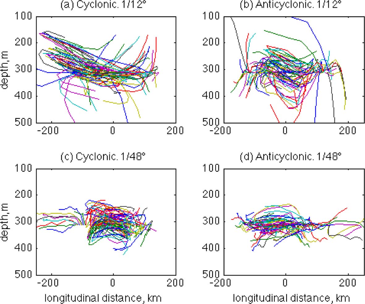
In order to examine this, vertical trajectories of flow particles are compared for the four cases. In Fig. 12, trajectories of arbitrarily selected particles are shown for the first five days in the x-z (longitudinal-vertical) plane. The time of particle tracking is chosen to be longer than that of the horizontal trajectories in Fig. 3 because it is necessary for the particles to have enough time to move significant vertical distances while circulating the rings. The depth of the particles’ initial positions is chosen to be z = 300 m because it is a depth at which a clear difference in Kz is seen (Fig. 11a), and it is also where the impact of small-scale structures can still be expected, as shown in Fig. 4. It is interesting to see that many of the particles in the LR simulations tend to move along the rings’ orbital trajectories. Specifically, it can be clearly seen that particles near the LR cyclonic ring are making their orbital motions on an inclined plane, so the larger vertical range of the particle trajectories can increase the absolute dispersion. Meanwhile, particles in the HR simulations are making more irregular trajectories without any directional tendency from the orbits of the rings. These more random and irregular vertical motions in the HR case are likely due to the small-scale structures. Similar to the horizontal particle motions that show higher variability due to small-scale structures in the HR simulations (Fig. 3), the vertical motions of HR flow particles also show higher irregularity and this may reduce absolute vertical dispersion rates around the initial depth. In the LR cases, these small-scale irregular particle motions are filtered out, so the dispersion rate is increased due to larger-scale orbital motions.
Fig. 12.
Longitidunal-vertical (x-z) trajectories of arbitrarily selected particles near each of the four rings for five days. The particles are initially located at z = 300 m.
An alternative to the absolute dispersion is the relative (or two-particle) dispersion, D2, which has been more widely used as it is more closely tied to turbulent and scalar mixing in the underlying flow field (Haza et al., 2008; Poje et al., 2010; Waugh et al., 2012; Özgökmen et al., 2012). The relative dispersion is defined as:
where the average is over all pairs of particles in the domain. Since the relative dispersion quantifies the meansquare separation of particle pairs, it may be more useful than the absolute dispersion in minimizing the effect of orbital trajectories because the separation of particle pairs is less influenced by the orbital motions. The corresponding relative dispersion coefficient is then given as:
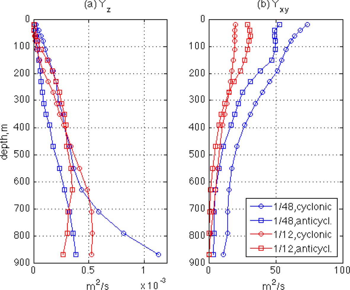
where D0 is the initial separation distance of particle pairs. In Fig. 13, the relative dispersion coefficients are calculated during the first 24 hours in the vertical and horizontal directions in panels (a) and (b) respectively. The initial distance, D0, is chosen as 0 m for Yz because the two particles are initially located at the same depth level, and ~2 km for Yxy. It should be noted that absolute dispersion rates in the horizontal direction are not considered in the present study because, due to the large orbital motions, the average distances of the particles from their initial positions is too large (so the dispersion rate is less accurate) to have meaningful values.
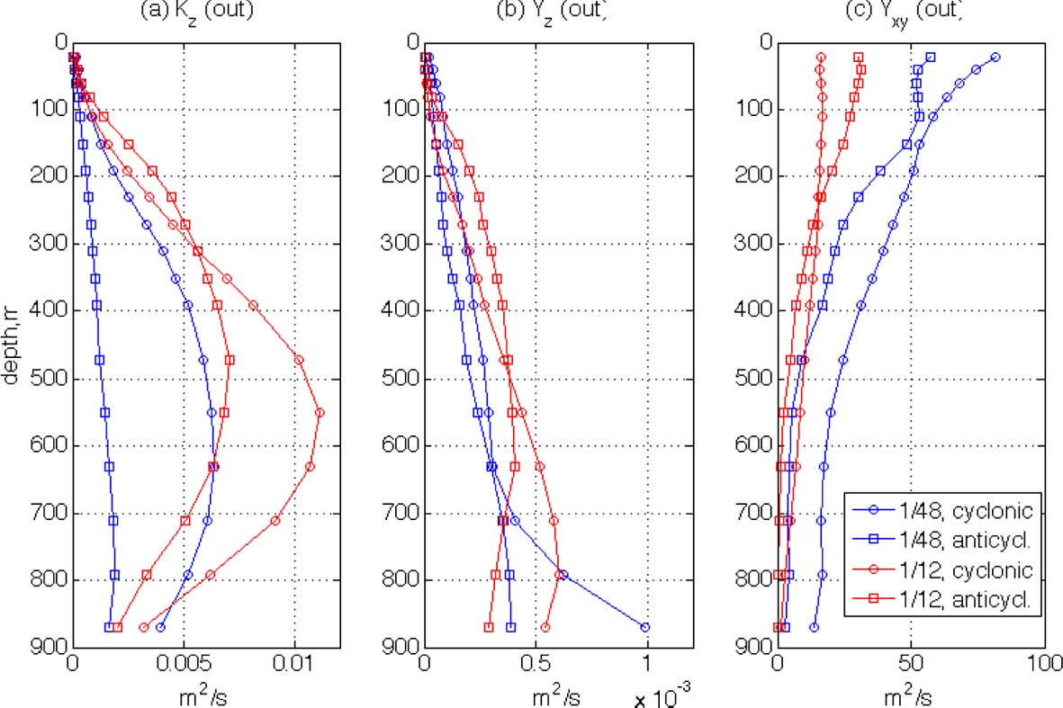
As shown in Fig. 13a, the relative vertical dispersion shows quite a different pattern from the absolute dispersion. First, the magnitudes of Yz are much smaller than those of Kz, as the Yz magnitudes are O(10-4 ~ 10-3 m2/s) giving more reasonable comparisons with other oceanic observations of eddy diffusivity. This reduction in Yz compared to Kz is expected from their definitions. Since Kz is calculated based on the average vertical displacement of particles from the initial depth, it involves the large-scale orbital motions such as those along the inclined orbital planes shown in Fig. 12a, which likely increases the magnitude of the dispersion rates. The relative dispersion, however, can reduce this effect if the initial separation, D0, of the particle pair is sufficiently small. Second, the difference in absolute dispersion between the two resolutions is much reduced for relative dispersion, as the magnitudes of Yz are now similar for the LR and HR rings. This also is expected: relative dispersion would increase if flows become more turbulent because flow particles move more randomly in such flows. As shown in Figs. 3 and 12, the particles in HR move more irregularly due to the small-scale structures. Hence this irregularity of particle motion may increase Yz in the HR simulation, and then reduces the difference in Kz between the two resolutions. The effect of small-scale flows can be seen in the horizontal relative dispersion coefficient Yxy which is higher in in the HR than the LR simulations (Fig. 13b), as in the results by Poje et al. (2010). The difference in Yxy between HR and LR is especially great at shallow depths, which confirms the role of small-scale structures in making horizontal particle motions more dispersive near the surface as can be inferred from Fig. 3. The magnitude of Yxy is greatest in the HR cyclonic ring and it decreases in the same ordering as the FSLE (Fig. 5) and the relative vorticity (Fig. 8a), which is different from that of the horizontal kinetic energy (Fig. 8b). This again indicates that the relative dispersion of flows near an ocean eddy may be closely related to the strength of the eddy’s rotational motion, but less related to the flow energy itself.
Fig. 13.
Relative dispersion coefficients for the first 24 hours: (a) the vertical components, Yz, and (b) the horizontal components, Yxy.
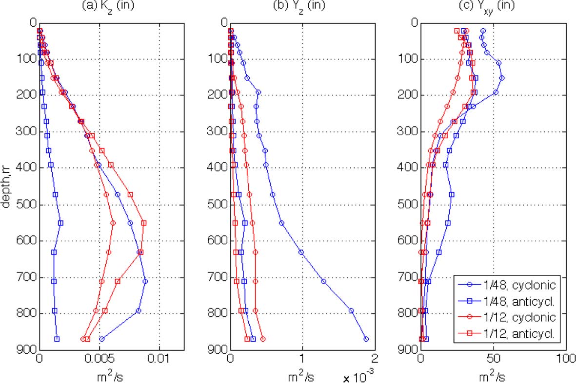
As described in the previous section, the flows associated with the rings can be partitioned into two different regions. One is the outer part of the ring where the FSLE ridges are strongly developed, forming eddy boundaries. In this area, strong mixing is expected along the convergent/ divergent regions and also near the hyperbolic points. The other region is the inner part of the ring where strong rotation occurs near the eddy core. As different behaviors of flow particles are expected in these two different regions, the vertical profiles of dispersion coefficients are calculated separately for each region. In Fig. 14, Kz, Yz, and Yxy are compared for the outer parts of the rings while Fig. 15 shows the same parameters for the inner parts of the rings.
The patterns of the dispersion profiles in the outer parts of the rings are similar to those averaged over the entire subsets inasmuch as greater magnitudes of LR horizontal absolute dispersions are reduced in the relative dispersions, indicating that particle motions in the outer parts represent well the dispersion patterns over the entire domains. This dominating dispersion rate in the region is due to the strong flow motions near the rings’ boundaries. The dispersion rates in the inner parts of the rings show many different patterns, as the magnitudes of both absolute and relative vertical dispersion coefficients decrease significantly in the LR simulations. This is likely due to the strong rotations inside the rings. Near the cores of the rings, flow particles are not easily dispersed, especially in the LR case, because of the rapid rotation. However, it is interesting to note that the magnitude of vertical relative dispersion in the inner part of the HR cyclonic ring increases significantly with depth compared to the other rings. This may be a result of small-scale structures that are actively developed even inside the ring as can be seen from panel (c) in Figs. 2 and 4. These small-scale flow structures possibly cause vertical flow motions and so increase vertical relative dispersion. In addition, the rapid increase in vertical relative dispersion of the HR cyclonic ring at greater depths may be related to the rapid decrease in the horizontal relative dispersion of the ring. The magnitude of Yxy in the inner part of the HR cyclonic ring is seen to be highest at shallow depths. However, Yxy values of the ring decrease below 200 m more rapidly than those of other rings. Therefore, it can be presumed that the turbulent flow energy that disperses flow particles in the inner part of the ring is partly converted from the horizontal direction into the vertical direction at greater depths. This relationship of decreasing Yxy and increasing Yz is only found in the HR cyclonic ring and not in the other rings, which may indicate that the characteristics of ocean eddies are diverse with many controlling parameters that are largely unknown. Another unique feature is found in the HR anticyclonic ring for which the magnitude of the absolute vertical dispersion coefficient, Kz, at depths of 200- 800 m is significantly smaller than that of the other rings. The small value of this property is not easily understood since other parameters for this ring have magnitudes comparable to those of the other rings. The diversity of vertical structures of large-scale ocean eddies has also been reported by Wilson at al. (2002) who observed four rings with dramatically different vertical structures and characteristics near the Brazil current system.
4. Conclusion
In the present study, three-dimensional structures of mesoscale ocean rings near the Gulf Stream recirculation region are studied through numerical investigations, comparing model outputs from two different horizontal resolutions. Analyses are made to examine LCSs using Lagrangian (FSLE) as well as Eulerian (OW) methods. Also, various dispersion coefficients of passive flow particles are calculated and compared in the vertical as well as horizontal directions. The relative (two-particle) dispersion shows more reasonable ranges of the vertical dispersion rates than the absolute (single-particle) dispersion, hence it is recommended for the analysis of vertical structures of ocean eddies. This judgment is based on the magnitudes of the dispersion coefficients. While the range of Kz magnitudes is O(10-3 ~ 10-2 m2/s), that of Yz magnitudes is O(10-4~10-3 m2/s). Although the magnitude of vertical dispersion coefficients of passive particles has not been verified in the ocean yet, it has been generally reported that the magnitude of vertical eddy diffusivity has a range O(10-5 ~ 10-4 m2/s) in ocean interiors (e.g., Kantha and Clayson, 2000). In the upper part of the ocean, however, the eddy diffusivity magnitude could be as high as O(10-3 m2/s) due to the activity of small-scale features (Richards et al., 2012). In addition, it should be recalled that the vertical motions and transports can be significantly increased if the flow turbulent energy increases due to such phenomena as eddy motions. Although measurement of such quantities is difficult, due to their small magnitudes compared to horizontal motions, there are previous studies that have reported the possibility of strong vertical motions near ocean eddies. Allen and Smeed (1996) solved the omega equation to calculate two-dimensional maps of vertical velocity based on observed data, suggesting that vertical velocity could be ~1 mm/s inside ocean eddies. Martin and Richards (2001) also reported similar results with upwelling/downwelling velocities up to 20 m/day within a mesoscale ocean eddy. The role of submesoscale structures on vertical velocities has also been studied, as Legal et al. (2007) reported high values of vertical velocities were found within small-scale filaments near mesoscale eddies. The sensitivity of grid size on vertical velocity has also been examined and high-resolution simulations that can resolve submesoscale structures can have high vertical velocities up to 20~30 m/day (Levy et al., 2001; Capet et al., 2008). Thus, the magnitude of the relative vertical dispersion coefficients found in the present study is believed to be within an acceptable range.
The effect of the small-scale structures is also investigated in the present study. Although the magnitudes of vertical dispersions in the HR simulations are not significantly higher than those of LR, it is found that the flow particles move more irregularly in the HR case, probably because of the small-scale flow structures present. The resulting irregular particle motions lead to enhanced HR relative dispersion compared to that of LR. The magnitudes of vertical absolute dispersions are too high, especially for LR rings, because the displacement of flow particles from the initial depth can be greatly magnified if the particles follow the rings’ inclined orbits. Therefore, the HR simulations give more realistic estimations than LR in terms of the vertical dispersion rates of fluid particles. The magnitude of horizontal relative dispersion is about O(105) times larger than the vertical dispersion. This is similar to the ratio of horizontal- to-vertical scales of motions in the ocean, implying that large-scale ocean rings have a two-dimensional structure with horizontal mixing expected to be much stronger than vertical mixing. The two-dimensionality of the ring is also verified from the three-dimensional FSLE structure that shows curtain-shaped features with extension of FSLE ridges to considerable depths indicating that ring boundaries are formed along these ridges throughout the water column.
Although no clear difference is found between the structures of cyclonic and anticyclonic rings, the convex shape of OW at the bottom of the anticyclonic rings may support the faster magnitude decrease with depth of the vorticity and kinetic energy profiles shown in Fig. 8. However, further studies are required to investigate the relationship of the eddy’s rotational direction with vertical transport, because a possible difference in the flow particles’ vertical motions, that may be caused by the opposite rotations of cyclonic/anticyclonic eddies, is not clearly observed in the present study. Instead of showing any directional tendencies, upward and downward vertical motions of flow particles occur evenly over the domain in and outside the rings. It should also be mentioned that the rings chosen in the present study show high variability in their characteristics though their horizontal flow energies and vorticity strengths are comparable. For example, in spite of the relatively high horizontal dispersion rate, the vertical dispersions of the HR anticyclonic ring are extraordinarily low compared to those of the other rings, and this is not clearly understood in the present study’s analysis. High variability in the characteristics of large-scale ocean eddies, which has been observed previously (Wilson et al., 2002), needs further investigation to find the unknown controlling parameters and their relations to specific eddy properties and structures


